
Project Overview:
T Solutions India (TSI) developed a 3D Transient Multiphase Flow CFD model to analyze Cold Thermal Energy Storage (CTES) ice system (Shell and Tube Heat Exchanger) to study the multiphase flow along with phase change inside the tubes and shell and to evaluate the freezing process to optimize ice storage
Objective:
The objective was to simulate the evaporation of refrigerant liquid and two phase (liquid & vapor) flow inside the tubes and to simulate the solidification and melting process inside the shell for water liquid and ice, to predict the ice formation with respect to time inside the shell and around the tubes
CFD Analysis:
A 3D Transient CFD Model was developed using Multiphase Model, Conjugate Heat Transfer, Evaporation and Condensation Model, and Solidification and Melting Model to analyze Ice growth inside Shell side of CTES system. CFD analysis was carried out for several minutes to analyze the evaporation of refrigerant liquid inside tubes, multiphase flow behavior inside tubes and shell, and ice growth inside the shell around tubes. CFD analysis included a comprehensive examination of flow pathlines, velocity, pressure, temperature, volume fraction of refrigerant liquid and vapor, volume fraction of water liquid and ice, evaporation inside tubes and ice growth inside shell around the tubes.
Result:
A 3D Transient CFD Model was developed to analyze Ice growth in a Cold Thermal Energy Storage (CTES) Ice system (Shell and Tube Heat Exchanger). CFD model results were in good agreement with experimental data.
Figure 1: Pathlines colored by Velocity Magnitude (m/s)
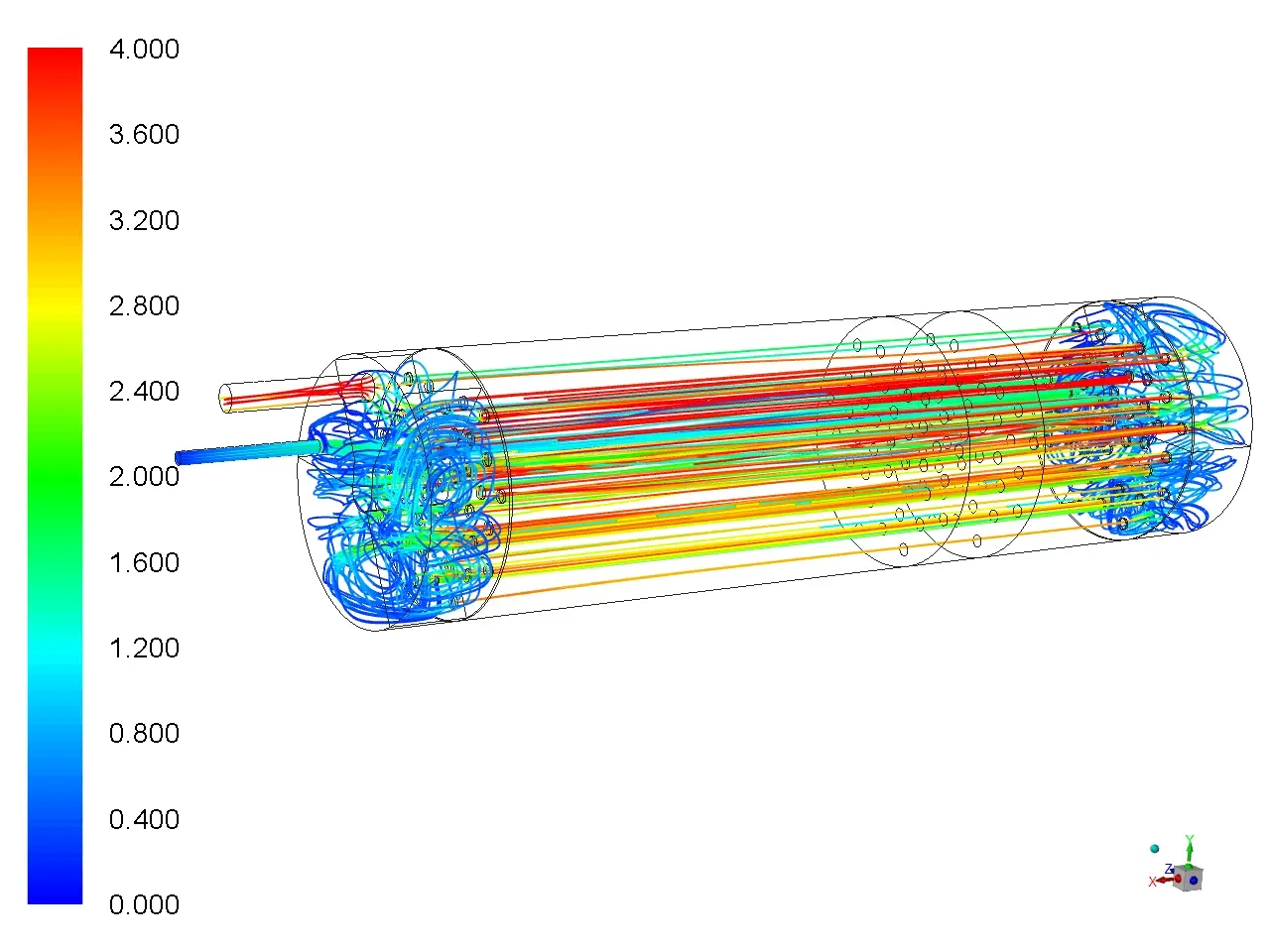
The above picture shows the flow pathlines in the tube side. Liquid refrigerant enters the tube, undergoes evaporation and flows as a mixture of liquid and vapor in the tubes.
Figure 2: Temperature Contours (degC)
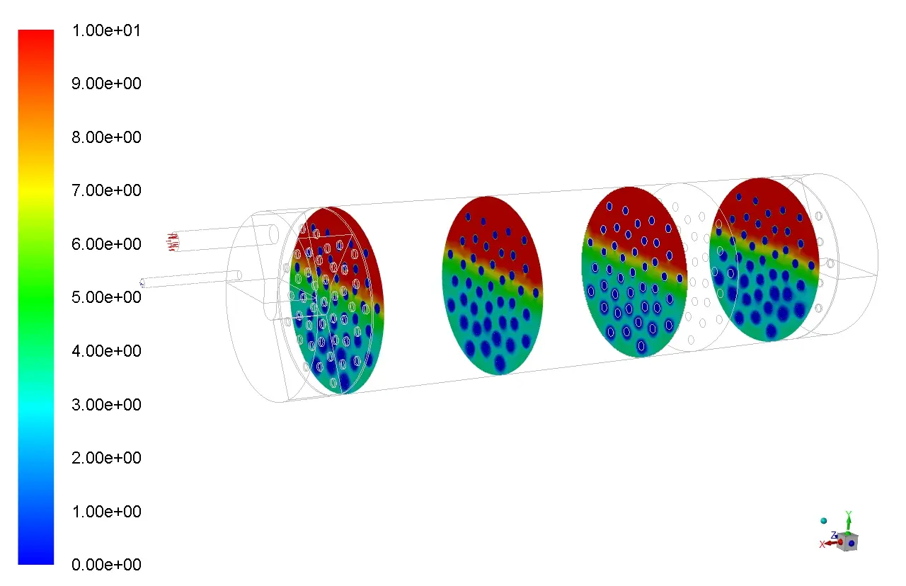
The above picture shows Temperature stratification due to density variation.
Figure 3: Ice Volume Fraction Contour during Ice Nucleation
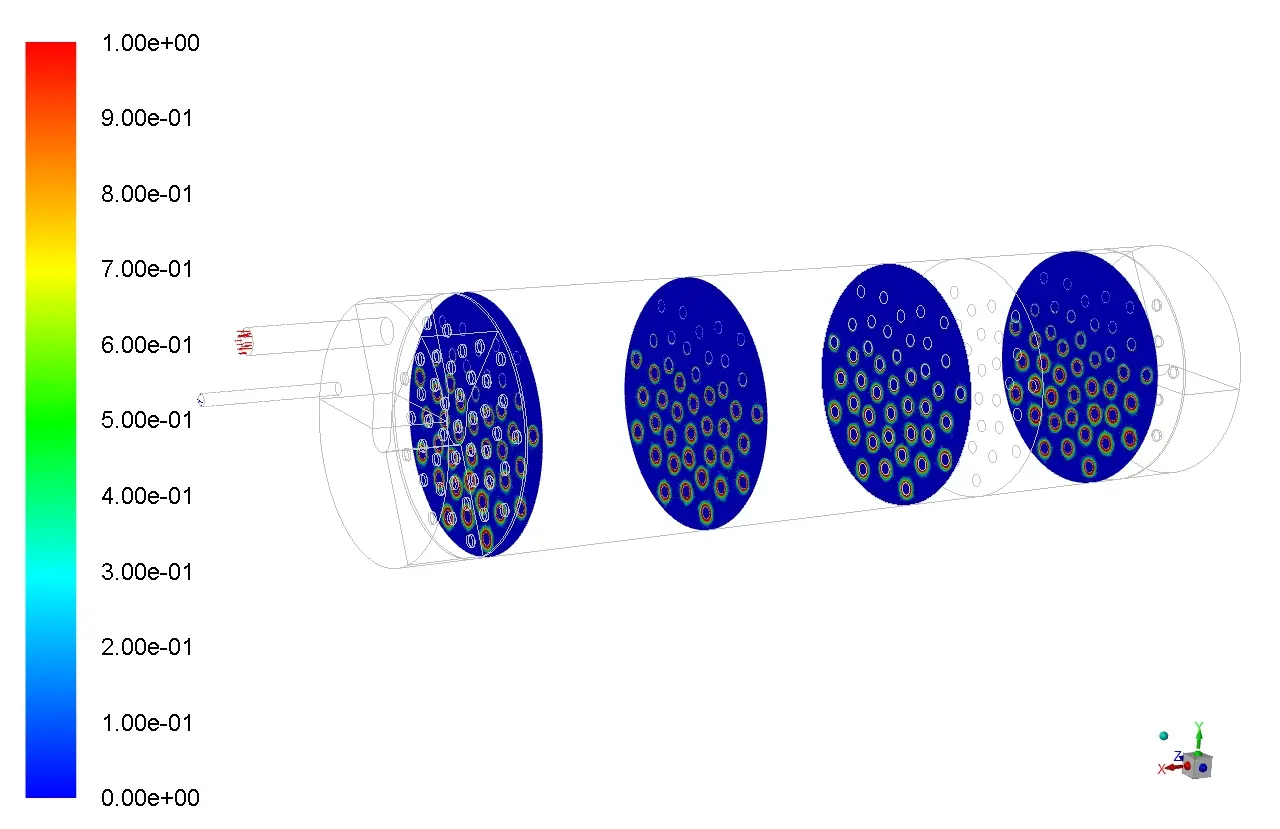
The above picture shows Ice nucleation at the bottom part of the shell.
CFD Model predicted well the Temperature Stratification inside the shell with colder water at the bottom, ice nucleation at the bottom and more ice formation at the bottom side of the shell.
Water has a unique density characteristic, being densest at 4degC.
Cold water sinks: During the charging phase, the coolant flows through the heat exchanger coils, cooling the surrounding water. As water near the tubes cools, it becomes denser and sinks, accumulating at the bottom of the shell.
Temperature Stratification: As this colder, denser water sinks, the bottom of the shell reaches the freezing point faster than the upper regions, leading to earlier ice nucleation.
Lower Convection Velocity: As the process progresses, natural convection forces slow down allowing the cold water to remain stagnant at the bottom and promote ice growth.
Figure 4: Ice Volume Fraction Contours
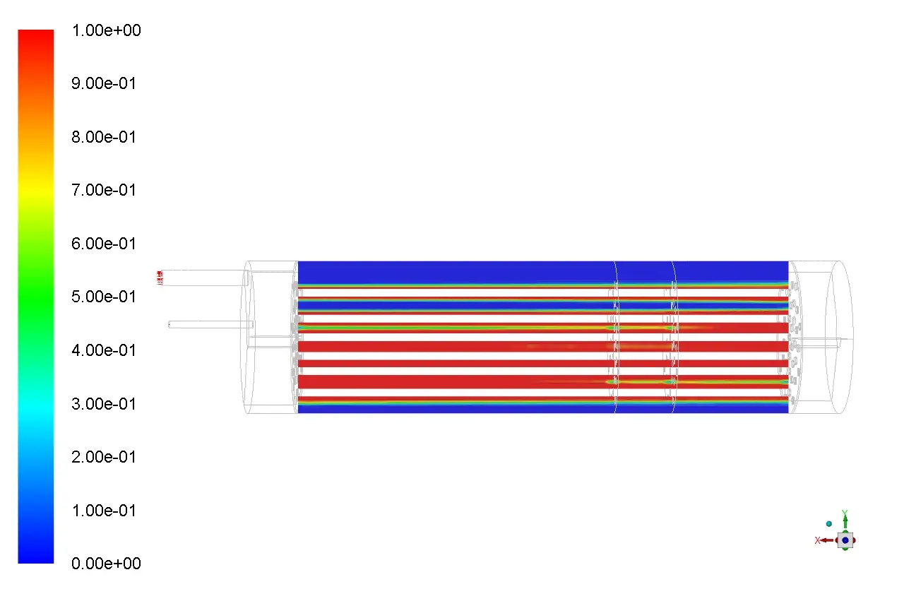
Figure 5: Ice Volume Fraction Contours
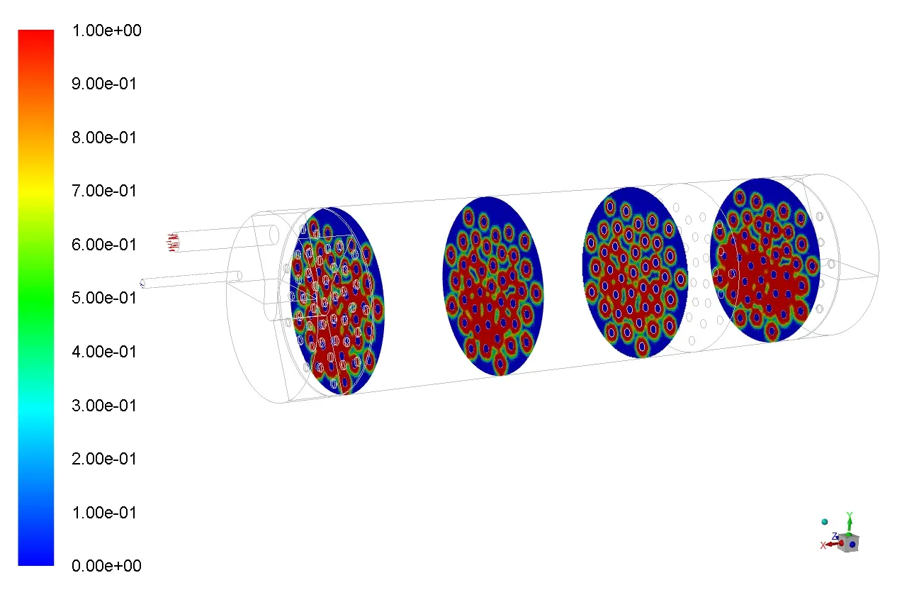
The above pictures show ice volume fraction contours inside the shell around the tubes after about one and half hours.
